In-Class Activity: Build an ALU
Introduction
In this mini-lab you will
build a 4-bit ALU using the Logic.ly simulator.
This activity may be done individually or in pairs or small groups.
Logic.ly
Start the Logic.ly simulator by going to
https://logic.ly/demo/.
If this does not work in your browser, you may download Logic.ly from
https://logic.ly/.
-
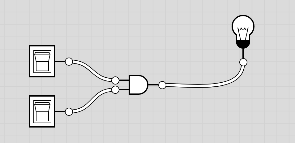
To become familiar with Logic.ly, add two Toggle Switches and an AND
gate to your circuit board. Wire the two switches to the AND gate.
Add a light bulb to your circuit board and wire the output of your AND
gate to the light bulb. Once you have this simple circuit set up,
experiment with flipping the switches to change the inputs to your AND
gate. Make sure that the gate does what you expect it to do.
- Extend your circuit diagram to create a Half-Adder with two inputs
and two outputs, the sum bit and the carry bit. You may use an XOR
gate if you want, or implement it with just AND, OR, and NOT gates.
"Run" it several times with different inputs to make sure it is
working correctly. (A full test of two inputs would consist of the
four possible permutations of the two inputs.)
(The slide on
Addition via Logic Gates
may be useful.)
-
A Full-Adder has a third input, the carry-in.
Combine two half-adders and an OR gate to create a one-bit Full
Adder (one bit addition with carry-in).
-
Add an AND gate and an OR gate to create a one-bit ALU. Since you
don't have a MUX, leave it with the three separate lines that would
go into the MUX, plus the carry-out. (So, 4 outputs altogether.)
(The slide on a
One-Bit ALU
may be useful.)
-
Create three more one-bit ALU's (copy-and-paste is your friend!)
and connect the carry-out of one to become the carry-in of the
next, constructing a four-bit ALU. Each bit will have three
potential outputs (AND, OR, and SUM), plus a carry-out going to the
next ALU. The carry-in of the least significant bit would still be
a Toggle Switch.
(The
MultiBitAdder slide
may be useful; click on the down-arrow on the page to display
the full page.)
-
Stop and Think: Looking at the
One-Bit ALU slide, what is the role of the
Binvert control line in implementing subtraction? Remembering that
integers are representing in two's complement, what should be the
carry-in of the least significant bit if the operation is
subtraction rather than addition?
Submit your results
Saving your work: If you have downloaded Logic.ly to
your own machine, you can go to File->Save As to save your
file. If you are running Logic.ly through the browser, you cannot save
the circuit board as a file, but you can take a screenshot to capture
your circuit diagrams.
Submit your solutions to the exercises above.